RECOMMENDED BOMBARDING PROCEDURE
(Internal
bombarding method)
©
COPYRIGHT 2006 Mark A. Snyder/SVP Neon Equipment
FOREWORD
Proper processing is essential to consistently obtain high quality,
long life luminous tubing. To accomplish this requires specific
equipment and an established procedure. The ‘bare bones’ pumping
system of days gone by, which consisted of a greased stopcock
manifold, 30-year-old 25 L/min. vacuum pump, 7.5 kva 15,000 volt
bombarder capable of only 650 mA. and using newspaper as a
“temperature gauge”, never produced consistent results – and it never
will. Add to this the seat-of-the-pants approach without any
instruments other than an oil or mercury manometer (instruments that
would otherwise give the technician information and control over the
operating parameters) and the procedure automatically became guesswork
at best.
The procedure described herein will provide a sound,
controlled approach to processing and allow the processing technician
to obtain consistent, repeatable results and the ability to produce
top quality tubes that will give years of trouble free operation.
EQUIPMENT
For this website version of our Recommended Bombarding Procedure it
will be assumed that one of our equipment packages is being used with
an appropriately sized bombarder and matching choke. Information on
each individual piece of equipment, such as manifolds, vacuum pumps,
the various instruments, etc., may be found elsewhere on this website.
GENERAL BOMBARDING PROCEDURE
It must be understood that the bombarding procedure is not an exacting
science. There are many variables to consider such as tubing diameter
and length, coated or un-coated tubing (and if coated, which coating),
electrode manufacturer and type of emission coating, size of
electrodes, number of bends in a unit, moisture content, etc. However,
there are certain parameters that must be followed in order to obtain
the desired results. Therefore, the following procedure should be
considered a guideline, but one that establishes these parameters.
For the procedure basis I will use the example of a 15mm diameter
tube, with 8 feet of glass (not including the electrodes) and coated
6500 white with 15mm, 80mA electrodes. In this case one electrode will
be a tubulated electrode. It will be found that when following this
procedure, using a tubulated electrode on one end will produce the
same consistent results as using two non-tubulated electrodes with a
side tubulation attached to the unit. Further, if the glass worker
prefers to side tubulate the unit, as some do and as is necessary
sometimes, it will also be found that it is not necessary to do so in
the middle of the unit to achieve even heating of the electrodes and
glass, provided a properly constructed and manufactured electrode is
used. Electrodes that heat inconsistently and/or unevenly are more a
function of the electrode rather than the procedure used.
STEP 1
To begin, the vacuum gauge should be turned off and the stopcock
leading to it should be closed. This will isolate the gauge tube
(sensor) from an inrush of air that would otherwise temporarily
contaminate the gauge tube. Although this will not permanently damage
it, it will require a considerable amount of time to degas before an
accurate reading can be expected. Vent the manifold to atmosphere by
slowly opening the air vent/blow hose stopcock. Attach the unit(s) to
be processed to the manifold.
RECOMMENDATION: Do not use rubber, vinyl or Teflon tubing, etc. for
this purpose. These materials exhibit tremendous outgassing properties
and some produce a phenomenon known as molecular permeation. Because
of this phenomenon, the material will never stop outgassing no mater
how long it is pumped and satisfactory vacuum levels may never be
realized.
STEP 2
Close the air vent stopcock and slowly open the main stopcock
completely. Allow the tube to evacuate for 20~30 seconds.
STEP 3
During STEP 2, connect the bombarder leads to the electrodes, and the
temperature gauge lead to the neon unit.
NOTE: The temperature gauge lead should be attached at least 6" to 8"
from either electrode but does not have to be in the middle of the
unit. Our tests have shown that the unit will heat quite evenly along
its entire length with the exception of tight bends and the glass
jacket surrounding the metal electrode shells.
CAUTION!
Check to make sure that the vacuum gauge is turned OFF and the
STOPCOCK for it IS CLOSED.
Set the bombarder choke control to the minimum setting, preferably
~150 mA.
STEP 4
Close the U-gauge stopcock. Using the air vent stopcock, admit 3~4mm
of air into the manifold as indicated by the pressure scale on the
U-gauge. This can easily be done by placing your index finger over the
open end of the side arm of the air vent stopcock. Opening and closing
the stopcock will allow a small amount of air into the manifold. It
may be necessary to repeat the procedure a couple of times to get the
desired pressure.
Bombard the tube using 150-200 mA of current until a glass temperature
of 100ºC is reached as indicated by the temperature gauge. Do not
allow the pressure to rise above 4~5mm. (If manifold pressure reaches
5mm before the glass temperature reaches 100ºC, turn off the bombarder
and reduce the pressure to 3mm by slowly opening and closing the main
stopcock, then begin bombarding again until 100ºC is reached before
proceeding.)
Turn off the bombarder and open the main stopcock completely. Let the
tube pump down for 30~60 seconds, depending on the overall size of the
unit (diameter x length), in this case (15mm single coated tube 8 ft.
long) about 30 seconds is sufficient.
WARNING! WHENEVER THE MAIN STOPCOCK IS GOING TO BE OPENED (for
whatever reason) THE BOMBARDER MUST BE OFF! FAILURE TO DO THIS CAN
RESULT IN A BOMBARDER FLASHBACK (DISCHARGE) THROUGH THE MANIFOLD AND
MAIN STOPCOCK. THIS IS VERY DANGEROUS AND CAN ALSO DAMAGE MANIFOLD AND
DIFFUSION PUMP COMPONENTS.
THIS IS VERY IMPORTANT! ALWAYS TURN OFF THE BOMBARDER BEFORE OPENING
THE MAIN STOPCOCK!
This “pre heat” procedure eliminates excessive moisture in the tube
that develops from storing the glass and during bending and splicing.
It is especially helpful when processing fluorescent blues and whites.
It removes the moisture that often causes premature discoloration in
coated tubes during bombarding. Although not entirely necessary, it
also helps in processing clear red tubes by reducing the chance of
dark spots developing and the metal electrode shell oxidizing during
the intense heating period at the end of the bombarding procedure.
STEP 5
Following the pre-heat and pre-evacuation procedure, close the main
stopcock and U-gauge stopcock. Using the air vent stopcock, admit 2mm
of air into the manifold as indicated by the pressure scale on the
U-gauge.
The length and diameter of the tube being processed and the capacity
of the bombarder usually determine the amount of pressure used to
begin bombarding. For example, a 10mm tube less than 4 feet long
should have an initial bombarding pressure of ~1mm. This is so the
glass will not overheat before the electrodes start to get hot. On the
other hand, a 15mm tube 12 feet long should have an initial pressure
of ~3mm if possible. This is determined by whether or not your
particular bombarder can light up a tube this large with this much
pressure in it. In our example we will use an initial pressure of 2mm.
NOTE: For proper bombarding the glass should get hot first and then
the electrodes. If the electrodes become red hot before the glass
reaches a temperature of at least 175ºC, the contaminants released
from the electrodes may deposit themselves on the cooler surface of
the glass. As the glass gets hotter some of the contaminants may cause
discoloration in fluorescent tubes as they are burned off the surface
of the fluorescent powder, thereby leaving dark spots and/or residue.
The discoloration may or may not get worse over time.
STEP 6:
After establishing the correct pressure, leave the U-gauge stopcock
closed in order to monitor the pressure inside the manifold while
processing the tube. Turn the bombarder on and adjust the current to
~200 mA. Continue to bombard until the glass temperature reaches
~150ºC as indicated by the temperature gauge.
It is necessary to monitor the pressure inside the manifold as
indicated by the U-gauge scale. As the glass becomes hotter the
pressure will begin to increase due to gases and vapors being released
from the surface of the glass and electrodes. In this example, any
time the pressure increases to more than 1-2mm above the initial
setting (up to 3-4mm), reduce the pressure to the initial setting of
2mm by slightly opening the main stopcock (with the bombarder off)
until the initial pressure is again obtained.
STEP 7:
At 150ºC adjust the pressure back to 2mm if necessary and increase the
current to 300 mA. (If smaller tubing is being processed, such as
12mm, it may not be necessary to increase the current at this point).
Remember to maintain the correct pressure range while proceeding.
STEP 8:
Continue to bombard until the glass temperature reaches ~200ºC. Reduce
the pressure to 2mm and increase the current to 400 mA and continue
bombarding. (On smaller diameter tubing reduce the pressure to 2mm and
increase the current to 250-300 mA).
The electrodes should now be getting hotter - a dull red-orange color
- and the glass will continue to increase in temperature.
STEP 9:
Maintain 2-3mm of pressure until the glass temperature is ~250ºC. At
250ºC reduce the pressure to 1 ½ to 2mm and increase the current to
10-15 times the electrode current rating. For example, for an 80 mA
electrode increase current to 800-1,200 mA. For a 30 mA electrode
increase current to 300-450 mA, etc. For our example increase current
to 800-850 mA.
NOTE: The maximum allowable current recommended by the electrode
manufacturer should be used if it is provided with the electrodes.
STEP 10:
Continue to bombard at 1 ½ to 2mm pressure at the maximum current for
the particular electrode used (in our case, 800-850 mA) until the
entire metal shell of the electrode is a bright, incandescent, almost
translucent, light shade of orange (sort of an illuminated pumpkin
orange) the entire length of the shell. This is very important! Electrodes that are not completely processed
will cause discoloration
in mercury tubes and cause red tubes to go dead prematurely. Depending
on electrode size, this final heating of the electrodes may take 10-20
seconds. However, it should be done in the shortest time possible
without excessive current to achieve the desired results.
If applied for too long of a time period, the high currents used for
processing the electrodes may damage the electrodes by sputtering
them. These high currents may also damage the stability of the
fluorescent powder causing decreased light output and premature
discoloration in mercury tubes.
By the time the electrodes are completely processed the glass
temperature should be
275-300ºC. However, care should be taken that the glass temperature
does not exceed ~310ºC.
NOTE: As a rule of thumb to determine whether or not the electrodes
were heated to a high enough temperature (technically ~1,200ºC), they
should exhibit some visible glow (though diminishing as the electrodes
begin to cool) for 15-20 seconds after the bombarder is turned off. If
they cannot do this, they were probably not heated to a high enough
temperature.
STEP 11:
Turn the bombarder off and completely open the main stopcock to
evacuate the tube. Open the U-gauge stopcock. Turn on the vacuum
gauge, but wait a few moments (~10 seconds) before opening the vacuum
gauge stopcock.
NOTE: With O-ring type stopcocks, “completely open” means to unscrew
and retract the white Teflon stopcock plug from the glass barrel as
far as possible without the upper most O-ring loosing its seal inside
the glass barrel.
STEP 12:
Immediately following Step 11, gently but thoroughly heat the
tubulation glass with the tipping torch between the neon unit and the
manifold with special attention given to the area where the final
seal-off will be made. However, if it is a mercury unit do not heat
the trap bubble that contains the mercury; heat the tubulation to
within ~½” of the bubble.
This step is done for several reasons: To prevent contaminant gases
that are being pumped out of the neon unit from condensing on an
otherwise cold tubulation, to burn off impurities that are present on
the interior surface of the tubulation glass, which would otherwise be
liberated when the final seal-off is made, and to prevent the mercury
from picking up contaminants as it is rolled through the tubulation
into the neon unit.
STEP 13:
While the unit is being evacuated, unhook the bombarder leads from the
electrodes and monitor both the temperature gauge and vacuum gauge to
confirm that the following minimum pump down criteria is met:
• By the time the glass cools to 200°C the pressure should be below 10
µ (microns).
• By the time the glass cools to 175°C the pressure should be below 5
µ.
• By the time the glass cools to 150°C the pressure should be at or
below 1 µ.
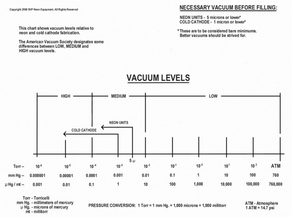
• Final vacuum before filling should be 1 µ or less.
NOTE: The above pump down speeds should be considered bare minimums.
Faster pump down times should be strived for.
More satisfactory pumping speeds are:
• By the time the glass cools to 200°C the pressure should be below 5
µ.
• By the time the glass cools to 175°C the pressure should be below 1
µ.
• By the time the glass cools to 150°C the pressure should be below
0.5 µ.
• Final vacuum before filling should be below 0.5 µ, but preferably
0.1 µ or less.
CAUTION!
Do not “flash” the bombarder to check for adequate vacuum. This can
damage the electrodes, the emission coating inside the electrodes and
the fluorescent powder. The damage may not be evident until the unit
has been in service for some time. “Flashing” the bombarder to check
for adequate vacuum may also cause a bombarder flashback through the
manifold, which may damage manifold and vacuum pump components.
STEP 14:
When the tube has cooled to 70-80°C, and the pumping
speed criteria has been met and a vacuum of 1 micron or less
(preferably less) has been obtained, the unit is ready for filling:
• Remove the temperature gauge lead.
• Close the vacuum gauge stopcock and turn the vacuum gauge off.
• Close the main stopcock.
• Close the U-gauge stopcock.
• Fill the unit with the desired gas to the correct pressure for the
size of tubing used.
• Immediately OPEN the U-gauge stopcock.
• Seal the unit off from the manifold.
AGING:
The finished unit should be ‘aged’ or ‘burned-in’ at 1½ - 2 times the
normal operating current of the electrodes used. For example, 30 mA
electrodes should be aged at 45-60 mA and 60 mA electrodes aged at
90-120 mA, etc.
Units filled with red gas should be the correct color immediately, but
should never take more than a few minutes to come up to full color.
Mercury units should be run for a few minutes before the mercury is
inserted to examine gas color, electrode firing, to insure a stable
discharge and to clean up any residue impurities. After this is done,
turn the unit off and allow the electrodes to cool. Insert the mercury
and roll the mercury from one electrode to the other, making sure some
mercury sticks to each electrode. Make the final seal-off of the
tubulation and age the unit by running it at the previously stated
burn-in currents until the mercury has vaporized throughout the entire
length of the unit and it is up to full color.
AGING CURRENT:
There will undoubtedly be some disagreement with the listed
recommendations. However, electrode manufacturers commonly use
excessive currents to do accelerated life tests on electrodes. They
have found that a properly processed tube should be able to operate at
3 to 4 times the normal operating current for several hours with no
adverse effects to the glass or electrodes. If a unit cannot do this
it simply was not processed correctly and/or inferior materials were
used to fabricate the unit.
PUMPING SPEEDS & FLUSHING:
If the pumping speeds listed previously are obtained it should not be
necessary to use any type of flushing gas or procedure. However, if a
flushing procedure is desired a simple additional step that can
further “clean” the tube follows:
After bombarding is complete and the unit has cooled to ~200°C and
there is absolutely no glow to the electrodes, admit a few millimeters
of neon gas into the tube and evacuate immediately.
The theory is that once a certain level of vacuum has been reached,
say 1 micron (1x10⁻³ Torr), all the remaining molecules of gas in the
tube are impurities, such as water vapor, carbon dioxide, etc. If an
inert gas such as neon is introduced, and the pressure is again
reduced to 1 micron, 50% of the remaining gas inside the tube will now
be neon gas and the other 50% impure gas. Therefore, the remaining
impure gas has been reduced by half. (Specifically, at a pressure of 1
micron there are 40 trillion molecules of gas left in every cubic
centimeter of ‘space’).
Actually, the end results are slightly more favorable than this
because the more common gases are pumped out more easily, thereby
leaving a higher percentage of inert gas as part of the remaining gas
load. The remaining inert gas will obviously not affect the operation
of the tube.
When performing this step always remember to close the vacuum gauge
stopcock before flushing. Exposing the gauge tube to inert gas will
not permanently harm the gauge tube, but it will require a period of
time to degas before accurate readings can be obtained.
COMMENTS:
Bombarding is a procedure that should not be rushed. A slow, gentle
approach will be found to be more effective than a fast, intense one
in terms of maximum light output, electrode life and the elimination
of contaminants that would otherwise effect the operation of the tube.
For example, if a piece of tubing is sustained at a temperature of
200°C for a period of 2 minutes, more impurities will be liberated
than if the same temperature were sustained for only a few seconds. As
well, if the electrodes are heated gradually the metal will be more
thoroughly degassed and the emission coating will be more completely
converted than if the procedure were rushed. Moreover, a slow ‘cook’
time is more desirable than a fast one.
Relative to processing the electrodes, a heating time of 5 to 6
minutes (depending on the particular electrode) with a final shell
temperature of 1,000°C will result in a shell that is roughly 90%
degassed. The shorter the bombarding time, the less the shell will be
degassed. At a bombarding time of 2 minutes and a shell temperature of
650°C (dull, dark red) the shell is only ~45% degassed. Generally
speaking, the less that the shells are heated and degassed, the less
the emission coating is processed and converted. Emission coating that
is not processed and converted will gradually contaminate the tube
over a period of time causing discoloration and tube failure.
I have visited shops where the ‘pumper’ tries to bombard units as fast
as possible, then have to let the unit pump down for 3-4 minutes in an
attempt to obtain a satisfactory vacuum as determined by ‘flashing’
the bombarder. The overall processing time for the unit ends up taking
at least 5-6 minutes, mainly due to the length of time required
attempting to outgas improperly heated glass and electrodes, with the
end results being unsatisfactory.
The procedure herein will take 4 to 5 minutes when processing coated
tubing and in the end will yield superior results. In the case of red
tubes pumping times can be reduced considerably by filling tubes ‘hot,
often at 150°C and even 175°C, provided the appropriate vacuum levels
are obtained before filling and the filling pressure is adjusted
accordingly.
|
TUBE PROCESSING QUICK
REFERENCE CHART |
|
FOR AVERAGE SIZE UNITS |
|
(15mm, ~8 feet long) |
|
|
|
|
|
|
BOMBARDING |
|
|
|
|
|
|
GLASS TEMPERATURE |
PRESSURE |
CURRENT |
|
|
UP TO 150°C |
2 – 4 mm |
200 mA |
|
|
150 - 200°C |
2 – 4 mm |
300 mA |
|
|
200 - 250°C |
2 – 4 mm |
400 mA |
|
|
250 - 300°C |
1 1/2 – 2 mm |
800 mA
or maximum
allowed for
electrodes used (10-15 x rating) |
|
|
|
|
|
|
|
PUMPING |
|
|
|
|
|
|
GLASS COOL DOWN |
|
VACUUM OBTAINED |
|
|
TEMPERATURE |
|
IN MICRONS |
|
|
|
|
|
|
|
|
|
GOOD
BETTER |
|
|
200°C |
|
- - -
< 10 |
|
|
175°C |
|
< 10
< 5 |
|
|
150°C |
|
<
5
< 1 |
|
|
75°C |
|
<
1
< 0.1 |
|
|
|
RECOMMENDED FILLING PRESSURES
(AT 70-80°C GLASS TEMPERATURE) |
|
|
|
|
|
|
|
TUBE DIAMETER |
PRESSURE (Torr/mm Hg.)
|
|
|
|
8 mm |
........................... |
17 mm |
|
|
|
|
9
mm |
........................... |
15 mm |
|
|
|
|
10 mm |
........................... |
13 mm |
|
|
|
|
11 mm |
........................... |
12 mm |
|
|
|
|
12 mm |
........................... |
11 mm |
|
|
|
|
13 mm |
........................... |
10 mm |
|
|
|
|
15 mm |
........................... |
9 mm |
|
|
|
|
18 mm |
........................... |
8 mm |
|
|
|
|
20 mm |
........................... |
7.5 mm |
|
|
|
|
22 mm |
........................... |
7
mm |
|
|
|
|
25 mm |
........................... |
6 mm |
HP, 4 mm LP |
|
(CLICK BELOW PICTURE TO ENLARGE)
|

