INSTALLING & TROUBLESHOOTING
THREADED GLASS COMPRESSION 0-RING CONNECTORS
Revised April, 2006
Copyright © 2006 SVP Neon Equipment - All Rights Reserved
The design of
borosilicate glass (Pyrex) neon manifolds and related components often
incorporates the use of various sizes of threaded glass compression
O-ring connectors, generally referred to as ‘threaded connectors’ or
‘connectors’.
From time to time equipment operators may suspect that a connector is
leaking. Therefore it is the intention of these instructions to
outline the proper installation and troubleshooting procedures
necessary to obtain and maintain a high vacuum connection when using
this particular type of connector.
INSTALLATION:
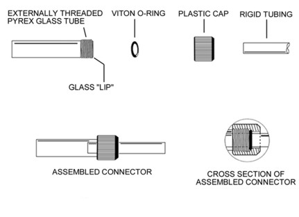
Refer to the diagram at the bottom to become familiar with the components
that comprise a connector and how these components fit together to
make a complete connection. From left to right: The Externally
Threaded Pyrex Glass Tube, the Viton O-ring and the Plastic Cap.
Furthest to the right is the tubing to be inserted through the cap and
0-ring and into the externally threaded glass tube. This tubing may be
a stopcock sidearm, debris trap arm or pumping attachment. It may also
be a metal tube from a metal needle valve used with high pressure rare
gas canisters, or any other rigid tubing.
CAUTION:
The external glass threads are precision cut and polished and are very
delicate. Bumping something hard against them such as another piece of
glass will chip the threads easily. The chipped thread may cause the
glass threads to crack when the cap is tightened if the chip is not
polished first to remove any sharp edges.
MAKE SURE HANDS ARE CLEAN BEFORE HANDLING COMPONENTS!
Make sure the O-ring, end of the glass thread (the “lip”) and rigid
tubing are perfectly clean. There should not be even a speck of dust
on them as it can create a leak path. THIS IS VERY IMPORTANT!
Most problems with leaks are the result of dirty O-rings!
STEP 1: Slide the plastic cap over whatever rigid tubing
is to be attached to the threaded connector.
STEP 2: Slide the O-ring over the rigid tubing after the
cap.
NOTE: DO NOT apply any type of lubricant to the
connector O-rings. The connectors rely on friction to function
properly. Any lubricant will defeat this purpose.
STEP 3: Pull the cap over the O-ring so that the O-ring
is completely inside the cap and against the inside beveled shoulder
of the cap.
NOTE: On some tubing/connector size combinations it
may be necessary to “work” the cap over the O-ring as some
combinations are a snug fit. This can be accomplished by sliding the
cap onto the tubing a considerable distance, sliding the O-ring up
against the cap and pulling the cap back over the O-ring until the
O-ring is all the way inside the cap. Another alternative is to use a
blunt instrument to push the O-ring inside the cap. Be careful not to
nick or puncture the O-ring or scratch the rigid tubing. The smallest
cut, pin hole or scratch will cause the connector to leak when vacuum
is applied.
STEP 4: Insert the rigid tubing into the externally
threaded glass tube and screw the plastic cap onto the glass threads
until the O-ring is seated against the beveled shoulder inside the cap
and against the ‘lip’ of the glass thread.
NOTE: On some tubing/connector size combinations it
will be necessary to continue tightening the cap until the O-ring
touches the rigid tubing around its circumference before final
tightening is done.
STEP 5: Once the O-ring is lightly seated against the
inside beveled shoulder of the cap, the lip of the glass threads and
the tube that is inserted through the cap and O-ring, continue to
tighten the cap another ¼ to ½ turn only.
CAUTION: DO NOT OVER TIGHTEN THE
CAP! DO NOT USE TOOLS TO TIGHTEN THE CAP! THE CAP SHOULD BE HAND
TIGHTENED ONLY!
STEP 6: After the connection(s) have been tightened and
they are under a hard vacuum check the tightness of the caps again to
make sure they are snug.
TROUBLESHOOTING:
If a connector is suspected of leaking there are four (4) basic steps
to follow to determine if a connection is physically undamaged and in
proper working condition. These four steps apply to any size
connector.
If the following four steps yield positive results and all components
of a connector are physically undamaged, it can be safely assumed that
the connector will achieve a high vacuum seal provided the components
of the connector are properly cleaned, assembled and tightened. When
properly cleaned, assembled, tightened and thoroughly outgassed the
connectors are capable of vacuum levels in the 10-8 Torr range, which
is well into the Ultra High Vacuum region.
WARNING! DO NOT TEST FOR LEAKS AROUND THE O-RINGS USING A TESLA
COIL (SPARK TESTER). THE DISCHARGE FROM THE SPARK TESTER WILL PUNCTURE
HOLES IN THE O-RINGS THEREBY CAUSING LEAKS AND MAKING IT DIFFICULT TO
TROUBLESHOOT A SUSPECTED CONNECTOR.
STEP 1 - CHECKING THE O-RING:
An O-ring stretching tool such as a tapered shaft of the appropriate
size should be used for this step. Disassemble the connector
completely. Make sure the O-ring is perfectly clean. Most leaks are
the result of dirty O-rings. Slide the O-ring onto the tool until the
O-ring stretches at least 25% to 30% beyond its normal size. If there
are any pin holes, nicks or cuts in the O-ring they will expand in
size and be much larger and easier to see. If an O-ring splits apart
while doing this then the O-ring had a defect in it.
Examine the entire surface of the O-ring including the inside
diameter. This can be done by “rolling” the O-ring on the tool until
the inside diameter is facing out. Examine the “face” of the O-ring,
which is the area that seals against the glass lip. These are the
critical areas that maintain the high vacuum seal. If an O-ring has
any defects or imperfections it should be replaced.
STEP 2 - CHECKING THE GLASS LIP:
With the connector disassembled, visually look at and thoroughly
inspect the very edge of the open end of the glass threads. This is
called the “lip”. This is the surface that the O-ring seals against.
The entire lip must have a very smooth fire polished surface. It must
not have any nicks, chips or even scratches in it. These will cause a
leak path past the O-ring and prevent the assembled connector from
obtaining a high vacuum.
NOTE: Minor chips in the glass threads do not affect
the O-ring seal. However, make sure any glass fragments from chipped
threads are not left in the plastic cap during assembly as this may
cause the glass to crack when the cap is tightened. Chipped threads
should either be fire polished or sanded with fine grit paper so they
are smooth and not sharp. Sharp edges may cause the glass thread to
crack when the cap is tightened.
STEP 3 - CHECKING O-RING COMPRESSION:
Examine the inside of the plastic cap, particularly in the area of the
beveled shoulder, for tooling slag, burrs or other debris. Install
only the cap and O-ring onto the glass threads. Screw the cap onto the
glass threads as far as it will go, thereby compressing the O-ring.
Look into the cap at the way the O-ring is being compressed. The
O-ring should be centered in the cap and the inside diameter of the
O-ring should compress evenly all around, 30% to 40% smaller than its
normal size. If the O-ring compresses unevenly, such as an oval or egg
shape, or is off center, it may not provide a good seal. In this case
the cap may be defective and should be replaced.
STEP 4 - CHECKING THE RIGID TUBING:
The rigid tube that is inserted into a connector is perhaps the most
overlooked potential problem area. Particular areas where problems
arise are where a glass gas flask connects to the gas flask stopcocks,
the tubulation connection and the connection between the mechanical
vacuum pump and diffusion pump and/or main stopcock, or anywhere lead
glass tubing is generally used. However, the problem can arise
anywhere a rigid tube is inserted into a connector.
The tube that is inserted into the connector must be free of any
scratches or other imperfections on its outside surface in the area
where the O-ring will make its seal around the tube. In the case of
glass tubing, the tubing should first be thoroughly cleaned and then
fire polished until the scratches are no longer visible. Care should
be used not to distort the diameter and/or circumference of the tube
from overheating it.
NOTE: Make sure glass tubing is thoroughly flame
annealed after fire polishing. If severe, remaining stress may cause
the glass tube to fracture when the O-ring is compressed around it.
Other types of rigid tubing should have scratches removed by polishing
with an appropriate method until the surface approaches the smoothness
of glass.
GENERALLY SPEAKING:
Cleanliness and meticulous attention to detail are extremely
important. Components that will be exposed to the inside of a high
vacuum system should be relatively free of finger prints and other
residue substances. If finger prints or other residue is evident on a
component that will be exposed to the inside of the vacuum system it
should be cleaned off before final assembly with a lint free cloth and
an appropriate solvent. The first choice of solvent for this purpose
is a high purity acetone with a low residue after evaporation. A
second choice is isopropyl alcohol. Lint free paper towels, such as
Bounty, are a good choice for this purpose provided they are white and
not a printed ink pattern. O-rings can be laid on a clean sheet of
white copy machine paper for final inspection before assembly.
O-RING MATERIAL & LIFE:
As with anything, there are inferior products on the market. Good
quality Viton O-rings should be used. Make sure the O-rings are first
quality Viton material. How hard or soft the material is is referred
to as the durometer. Use a number 75 durometer Viton O-ring for best
results. O-ring suppliers and manufacturers typically call these V75.
V60, V90, etc. Other durometers are also available, but V75 is the best
choice for this purpose. (Some suppliers offer V70 O-rings which is an
acceptable substitute).
Good quality V75 O-rings have been known to last more than ten (10)
years under normal use without need for replacement. If the O-ring is
less than two years old, defects are usually the result of neglect,
over tightening or some other form of abuse.
TROUBLESHOOTING
QUICK REFERENCE GUIDE
1) Check the O-ring for dirt & debris, pin holes, nicks, cuts or other
defects.
2) Check the threaded glass “lip” for scratches, nicks or chips.
3) Check for correct centering and O-ring compression with the plastic
cap.
4) Check the rigid tube for exterior scratches and other
imperfections.
5) Tighten the connector according to these instructions.
| |
|
|
| |
|
|
|
|
| |
THREADED CONNECTORS |
|
| |
|
|
|
|
| |
CONNECTOR SIZE |
ACCEPTS TUBING SIZE |
O-RING SIZE |
|
| |
#7 |
4 mm to 7 mm
(5 mm Works best) |
107 |
|
| |
#9 |
7 mm to 9 mm |
110 (or 109) |
|
| |
#15 |
12 mm to 15 mm |
206 |
|
| |
#18 |
15 mm to 19 mm |
208 |
|
| |
#25 |
22 mm to 25 mm
|
317 |
|
| |
|
|
|
|
| |
O-RING MATERIAL:
VITON
O-RING DUROMETER: 75
|
|
|
|
SVP
Neon Equipment
(Silica Vacuum Products)
113 Leventis Drive, Suite A
Columbia, South Carolina 29209
Ph. (803) 783-1165
www.svpneon.com
|
|

