|
|
SVP
BOMBARDING TEMPERATURE GAUGE
| |
|
|
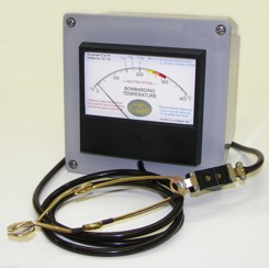
The SVP Bombarding
Temperature Gauge is
the only instrument of its kind on the market
specifically designed for high voltage luminous
tube processing. It is unaffected by the high
voltage electromagnetic field (corona discharge)
produced by the bombarder as are other types
of instruments and mediums.
The Simpson Self-Shielding Annular Pivot &
Spring-Loaded Jewels meter assembly is the
highest torque to weight ratio meter available.
The meter assembly is enclosed in a PVC
meter box and is completely self-powered. It
does not require batteries or other electrical
source to function.
|
 |
|
The temperature
sensor is a clamp-on unit, which ensures positive contact with
the glass. The sensor is encapsulated in a heat sensitive glass
fiber material that protects the sensor from oxidation. The
thermocouple wire is sheathed in high temperature silicone
rubber tubing rated at 600°F and is 60” long. This allows
stationary placement of the instrument without having to move it
with each processing cycle. (Custom lengths are available)
The large 4½” meter face is easy to see and truly unique. It
provides the processing technician with at-a-glance information
during the heating stage as well as the glass cool- down stage -
something other gauges, crayons and paper simply cannot do.
SUMMARY:
A bombarding temperature gauge is one of the four instruments
essential for proper luminous tube processing. A specific glass
temperature is necessary to insure that the maximum amount of
contaminants and impurities are released from the internal
surface of the tubing. If allowed to remain, these impurities
will affect the life, efficiency and overall quality of the
finished unit. In red tubes excessive impurities will cause
premature failure. In mercury discharge tubes it will cause
premature and unnecessary staining and discoloration. Therefore,
a specific glass temperature allows for highly effective
degassing of the tube and at the same time ensures that the
glass is not overheated, which may damage phosphor coatings and
the glass structure.
The SVP Bombarding Temperature Gauge is unique from other
meters/gauges and methods. In addition to being unaffected by
the high voltage corona discharge produced by the bombarder as
are other instruments, crayons and mediums, the meter face has
specific markings for the heating stage that correspond with
most electrode manufacturers bombarding recommendations. The
meter face also incorporates specific markings to compare glass
cool down temperatures with the speed of evacuation* following
the bombarding cycle**. This ensures that the unit is being
evacuated at a fast enough rate compared to specific glass
temperatures to ensure that re-absorption of the contaminants
released during bombarding does not occur. (The temperature at
which re-absorption begins is approximately 175ºC as the glass
cools***.) The large 4½” analog meter face in conjunction with
these specific markings provides the processing technician with
at-a-glance information as opposed to trying to focus on rapidly
changing digital numbers during the critical stages of
processing, or guessing at what the glass temperature may be if
a temperature gauge is not used at all.
* In addition to the SVP Bombarding Temperature Gauge, a high
vacuum gauge is necessary to accomplish the
comparison between glass cool down temperatures and the vacuum
levels obtained.
** SVP Neon Equipment is the only equipment manufacturer who
recommends specific values for evacuation speed vs.
glass cool down temperature.
*** Extrapolated from a graph produced by Sherwood, Westinghouse
Electric and Manufacturing Company. |
|
|
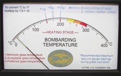
METER FACE DETAIL:
The first things you will notice in contrast to
other temperature gauges are the various
colored markings on the meter face. Each
marking has a specific meaning and purpose.
They are placed at these temperatures to
reference the designated temperatures during
various stages of the processing procedure.
Once the processing technician is familiar with
them the instrument will be invaluable in helping
the technician to produce consistent, repeatable
and reliable results, which will eliminate much of
the guesswork from the processing procedure.
|
|
|
Along the lower portion of the scale, the red lines
at 150°C and 200°C are temperatures at which
the manifold pressure and bombarding current
should be adjusted, following the guidelines
set forth in our discourse titled
Recommended Bombarding Procedure.
For the yellow, orange and red temperature ranges and corresponding
numbers there is a legend in the lower left corner of the meter face
with a short explanation of the various ranges: 1- Minimum glass
temperature; 2- Acceptable glass temperature; 3- Preferred glass
temperature.
Some of these temperatures are also points of pressure and current
adjustment while processing. These are also covered in more detail in
our Recommended Bombarding Procedure.
In
general, the yellow temperature range between 225ºC and 250ºC should
be considered a bare minimum, marginal glass temperature. The orange
temperature range between 250ºC and 275ºC is a satisfactory glass
temperature provided a fast pumping system is used and reasonable
lengths of tubing are being processed. The red temperature range
between 275ºC and 300ºC is the preferred glass temperature range for
thorough processing. The red temperature range will release more
impurities and contaminants from the interior surface of the glass and
will allow a longer evacuation period before the glass cools to the
re-absorption temperature of 175ºC.
Along the upper portion of the scale you will notice three blue lines
with symbols above them along with corresponding blue text in the
upper right corner and lower right corner. The text in the upper right
corner signifies that the blue lines and symbols to the left are for
reference during the evacuation stage. These numbers are to be
compared to the readings on a high vacuum gauge (ultimate vacuum
gauge, micron gauge, etc.) to ensure that the tube is being evacuated
at a sufficient rate of speed. The blue text in the lower right corner
indicates that these are the Recommended Maximum (worst) vacuum gauge
readings that should be obtained during glass cool down. Better vacuum
levels should be strived for. The symbol < means “less than” and the
symbol µ means “microns” (a vacuum measurement, which is the same as
mTorr or millitorr). So, the symbol <10µ directly above the 200ºC mark
means “less than 10 microns”.
For example: After the unit has been bombarded to the proper glass
temperature the bombarder is turned off. The main stopcock is fully
opened to evacuate the tube. The high vacuum gauge is turned on and
the stopcock for it is opened. The tube begins to cool as indicated by
the temperature gauge. When the needle on the temperature gauge drops
to 200ºC the level of vacuum as indicated by the vacuum gauge should
be <10µ (less than 10 microns). When the glass has cooled to 175ºC the
level of vacuum indicated by the vacuum gauge should be <5µ (less than
5 microns), etc. If these marginal vacuum levels cannot be obtained,
then the vacuum system does not evacuate quickly enough and quality
units will be impossible to produce.
|
|
 |

Proudly
Made in
the USA |
 |
|
|
|